
In the Matter-Wave Lab we build an atomic Sagnac interferometer to sense rotation. In particular, we want to use magnetically guided atoms, almost like a fibre optic gyroscope. However, our approach is based on a scheme that does not require free propagation of matter waves but uses atoms in superposition of being tightly trapped at different locations. This can be used to sense rotation by measuring the relative phase of the superposition after moving the traps around a closed path in opposite directions.
In general, the Sagnac phase after a full loop 

where 


Our experimental approach uses the state dependence of radio-frequency dressed, magnetic traps of a particular configuration. In such traps, the Larmor precession of atoms is excited, which causes a different response and different potential energy for atoms with different g-factors. By putting atoms first into a superposition of having either a positive or a negative g-factor by flipping their nuclear spin, we can then spatially separate the two.
On the left, the idealised shape of the potential is shown for an atomic state with positive g-factor. It arises from a combination of a ring-shaped magnetic quadrupole field and a particular radio-frequency polarization. In fact, this configuration forms two independent circular paths (yellow) that can both be used as an interferometer. An additional radio-frequency field generates state-dependent traps (orange) that move around the loops. For a negative g-factor, the traps move in reverse directions. The fact that the setup simultaneously generates two interferometers with opposite senses, will later allow us to carry out a differential measurement, thus correcting for any technical bias in the measured rotation.
This trapping scheme is combined with magnetically trappable clock states of rubidium, allowing us to generate coherent superpositions of atoms. The interferometer sequence starts by initialising atoms in one of the clock states (spin down) and generating a 50/50 superposition with a π/2 microwave pulse. As the additional, linearly polarised rf-field can be decomposed into 

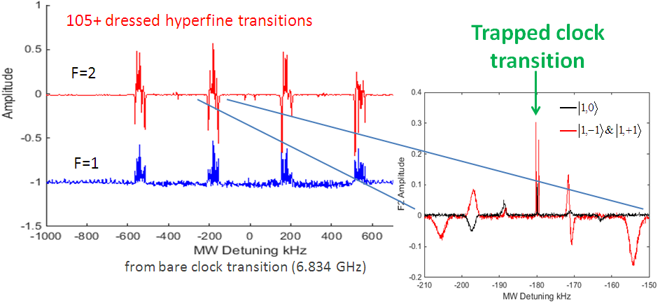
In a somewhat different configuration, and in collaboration with the Cretan Matterwaves Team, we have recently shown that radio-frequency dressing can indeed be used for state-dependent trapping of these states.
The dressing with radio-frequency adds interesting complexity to the possible transitions between different hyperfine states. In the corresponding microwave spectrum, each of the original frequencies becomes a group of spectral lines. And almost every transition between any pair of states becomes allowed. Some of these transitions are (almost) independent of the field amplitudes, leading to sharp spectral lines while other transitions are broadened due to environmental field noise.
Our next steps aim at building an atom chip based Sagnac interferometer.
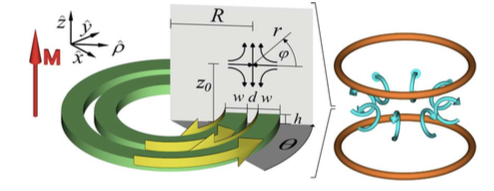
The ring-shaped quadrupole field that we require can be generated in a surface based approach. We can use either two concentric magnetic rings, or equivalently, four counter-propagating, circular electric currents.
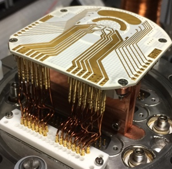
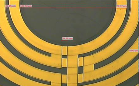
Our collaborators at Ben-Gurion University have built an atom chip for us. It features two layers of concentric wires that can generate a trapping ring of 400 micron diameter. The two layers are required to overcome field distortions introduced by the lead wires. The lead wires in the two layers are placed on opposite sides of the ring such that they can be avoided by switching between layers half way through the interferometeric sequence. The chip itself will be mounted and electrically bonded to an ultra-high vacuum (UHV) compatible, multi-layer printed circuit board (PCB). Several coils in the PCB provide the necessary fields to capture, transport and compress atoms into the final radio-frequency dressed trap.
We start from a magneto-optical trap with roughly 
The false colour images below give some impressions from the actual loading process.
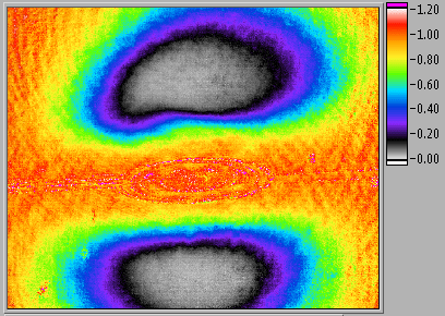
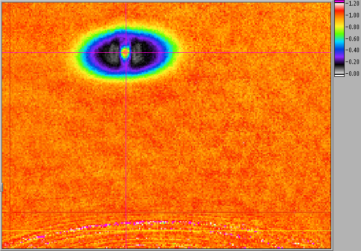
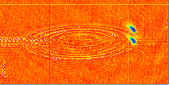
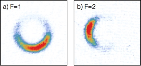
Recently, we successfully demonstrated the transport of atoms through the ring-shaped potential. This process is state-dependent, but only one internal state with positive g-factor is used in this animation.

You must be logged in to post a comment.